
Course:
BLOOM - FLL BIOGLOW Robot

The BIOGLOW season invites students to explore biodiversity, ecosystems, and the ways science and technology can help us understand and protect the natural world. Through the Robot Game, teams use LEGO® robots and creative mechanisms to complete missions that represent challenges connected to this year’s theme.
Before we start building BLOOM, however, we are going to approach the Robot Game from a different perspective.
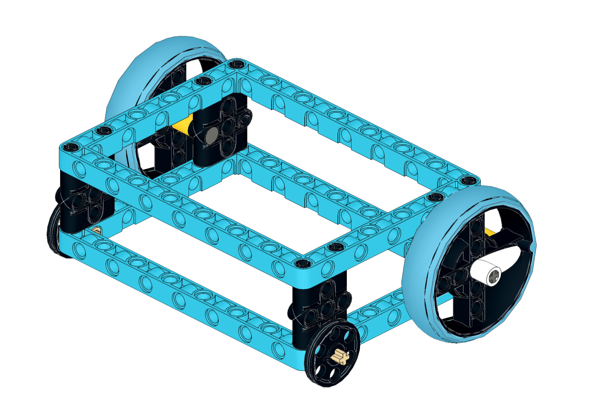
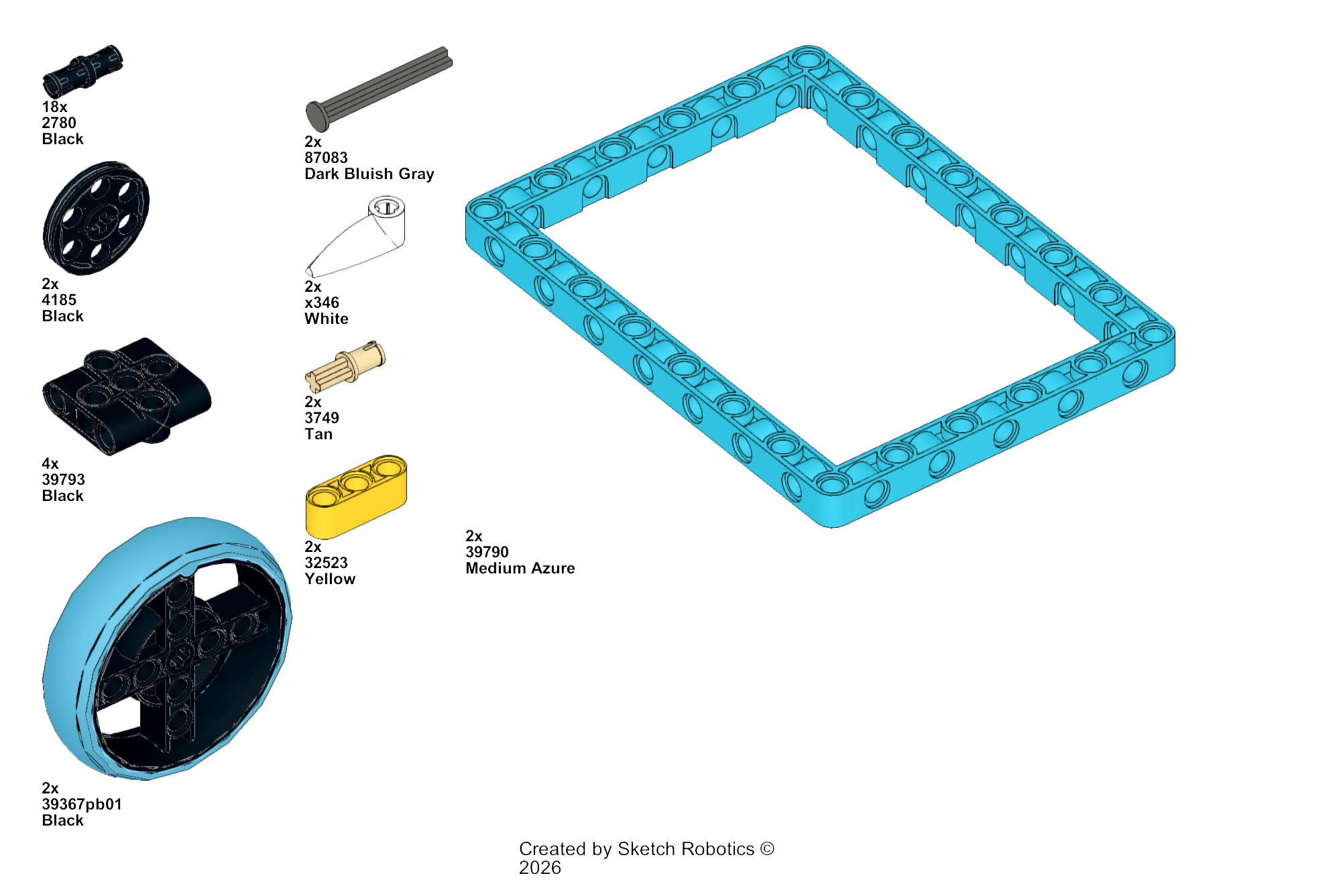
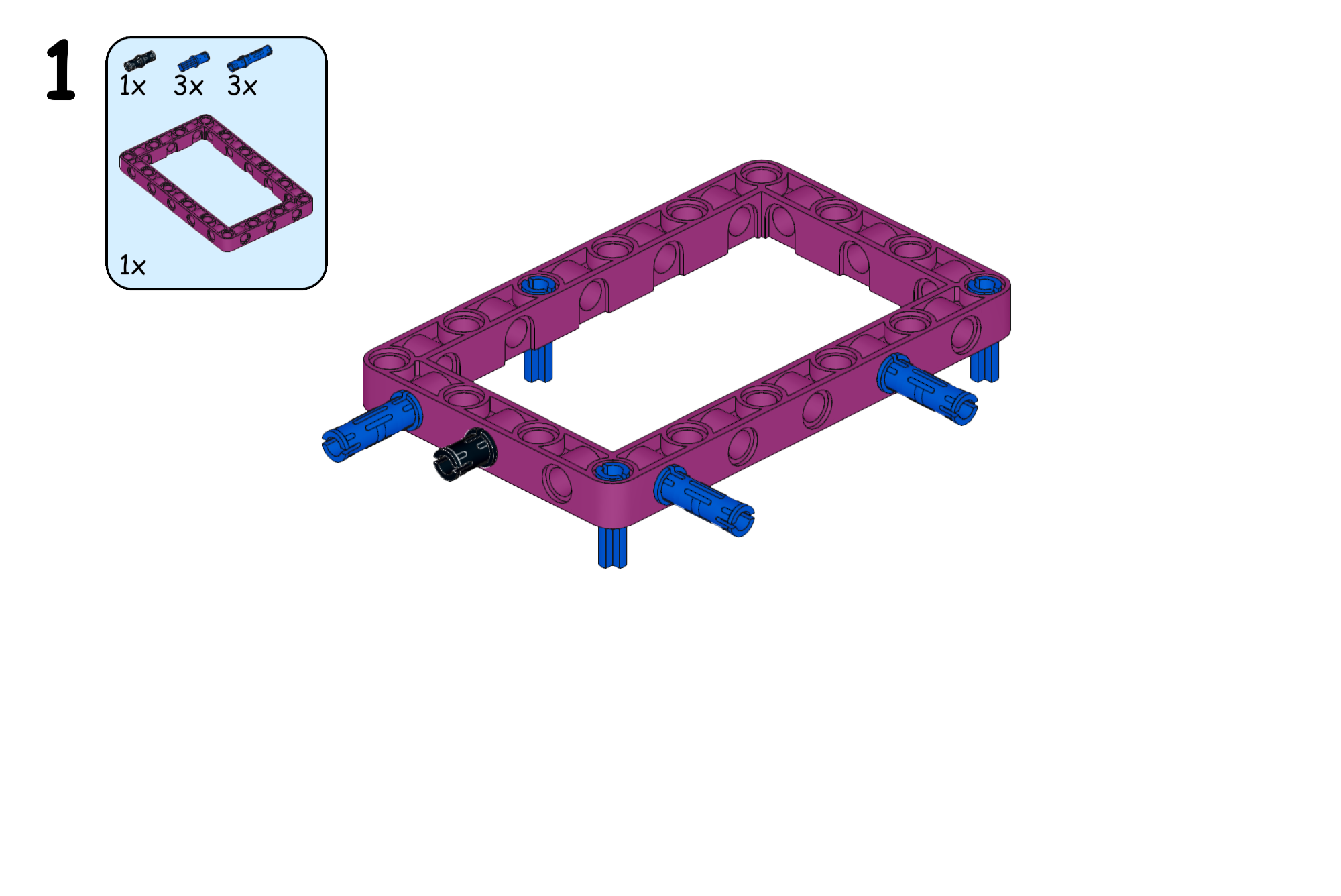
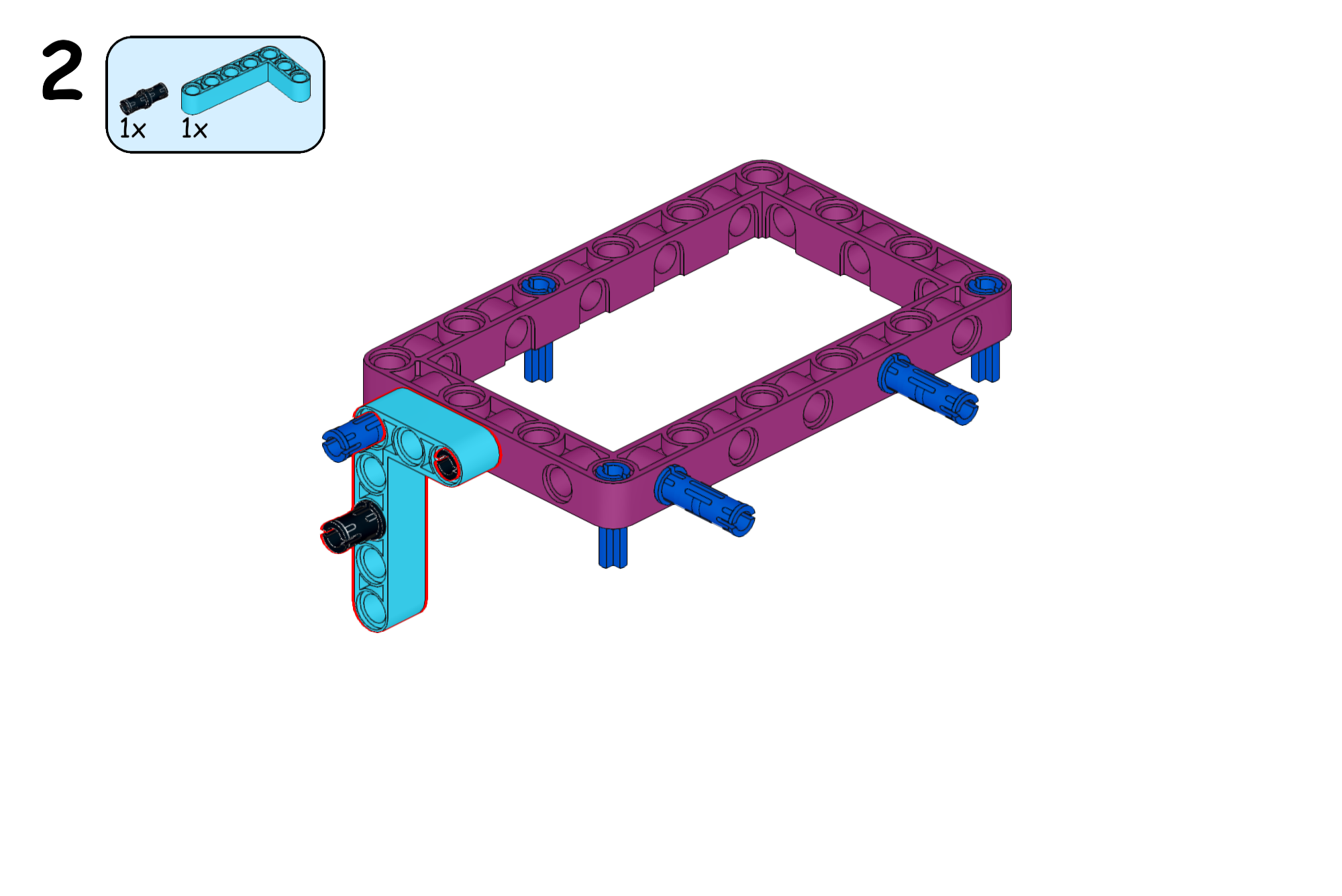
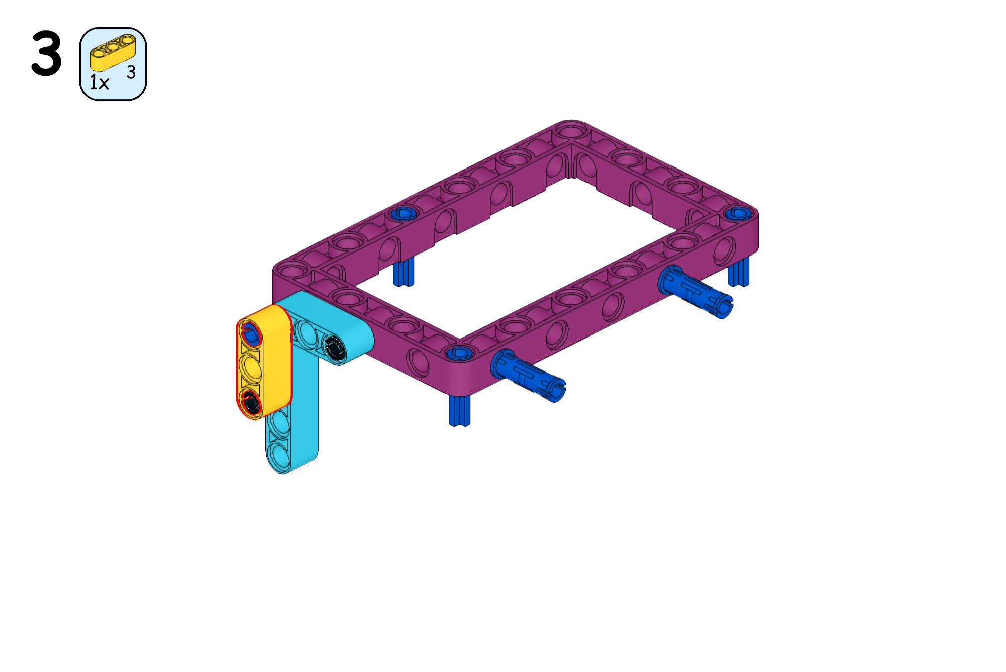
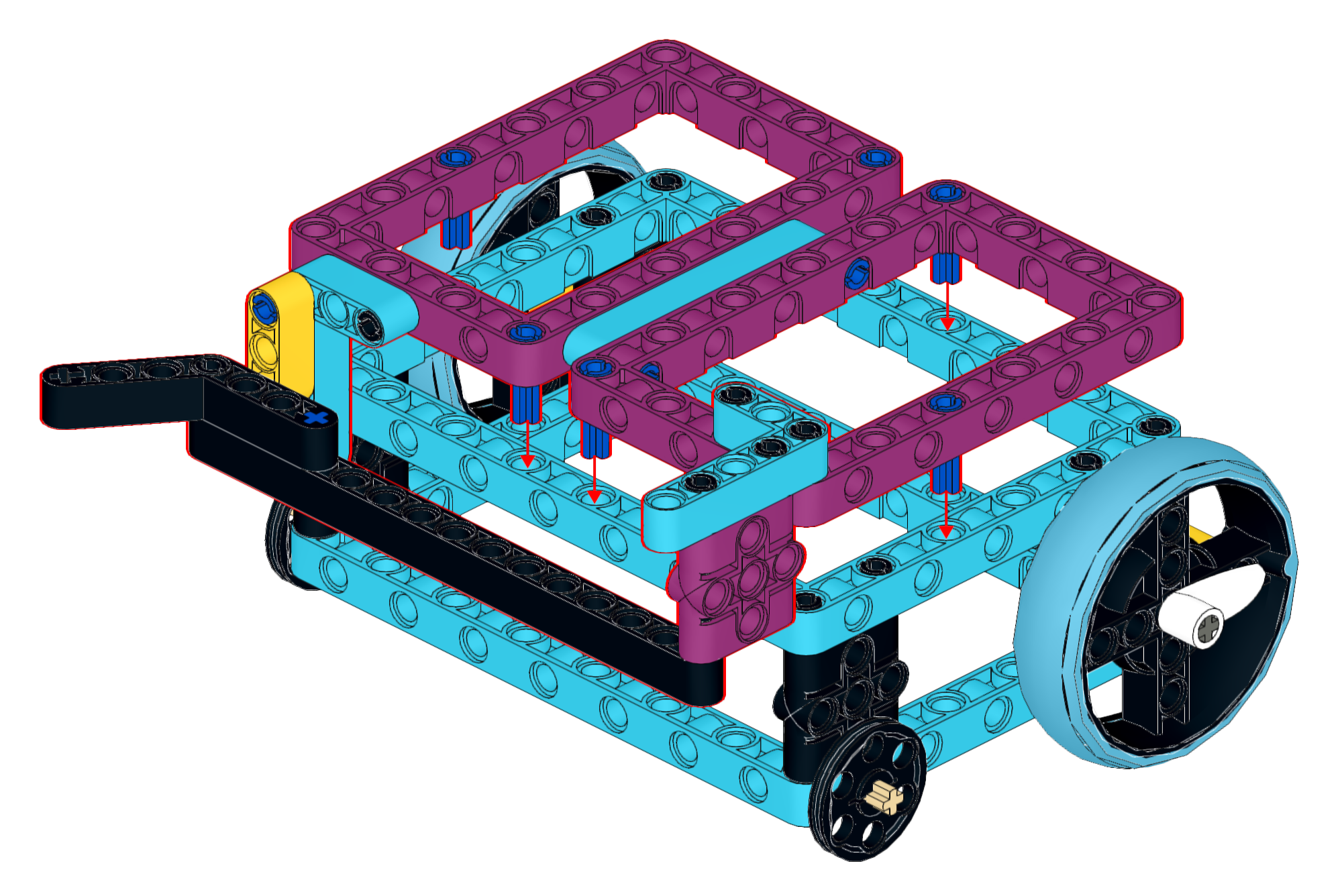
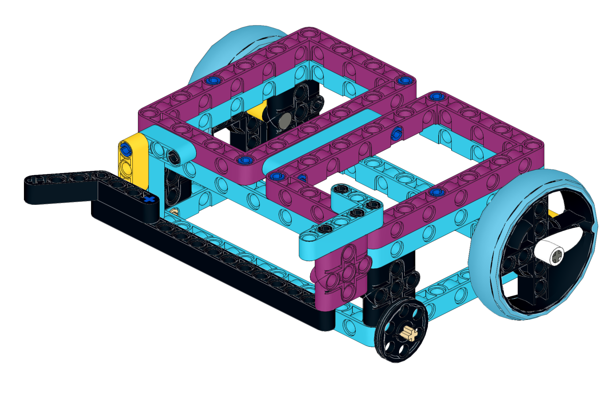
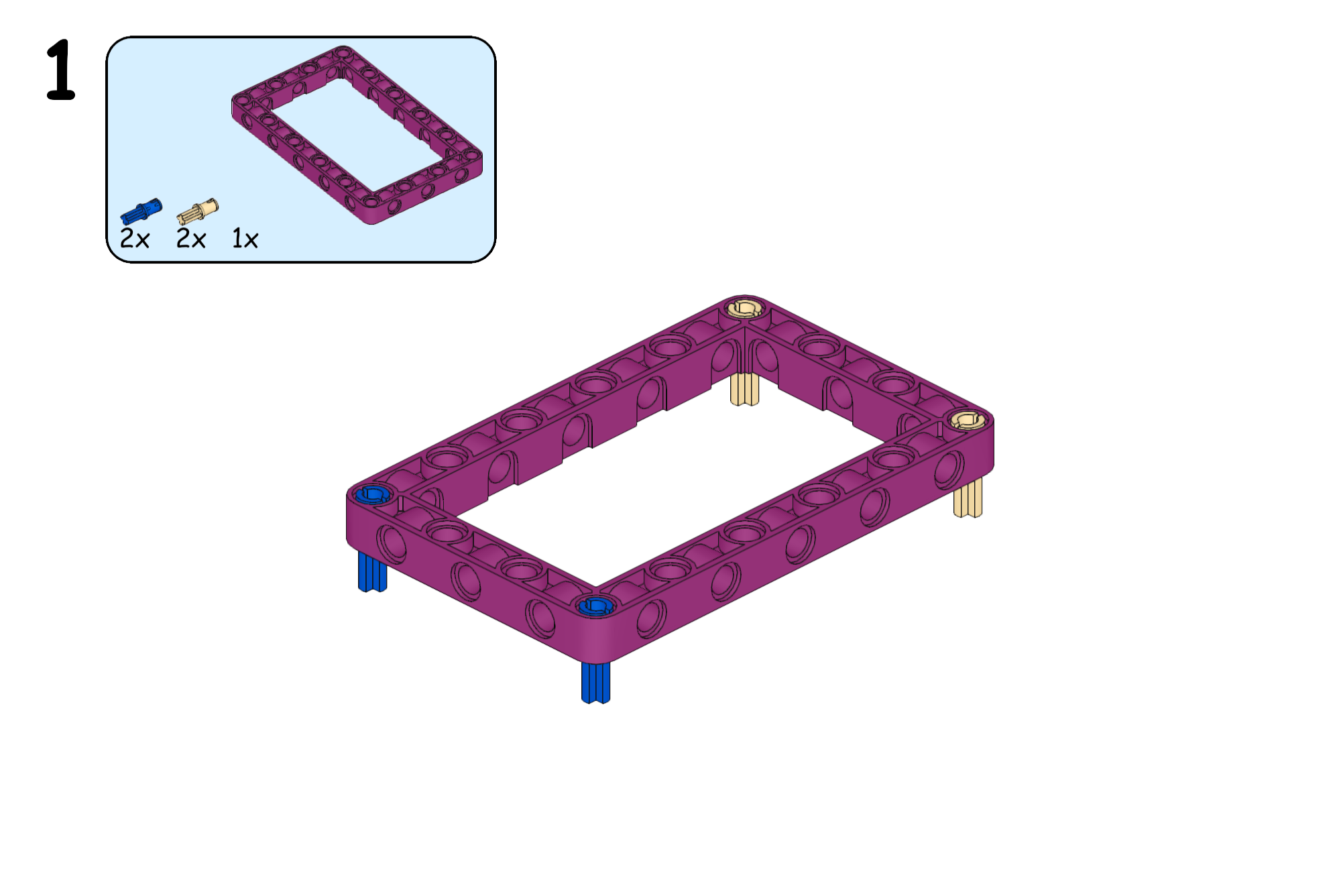
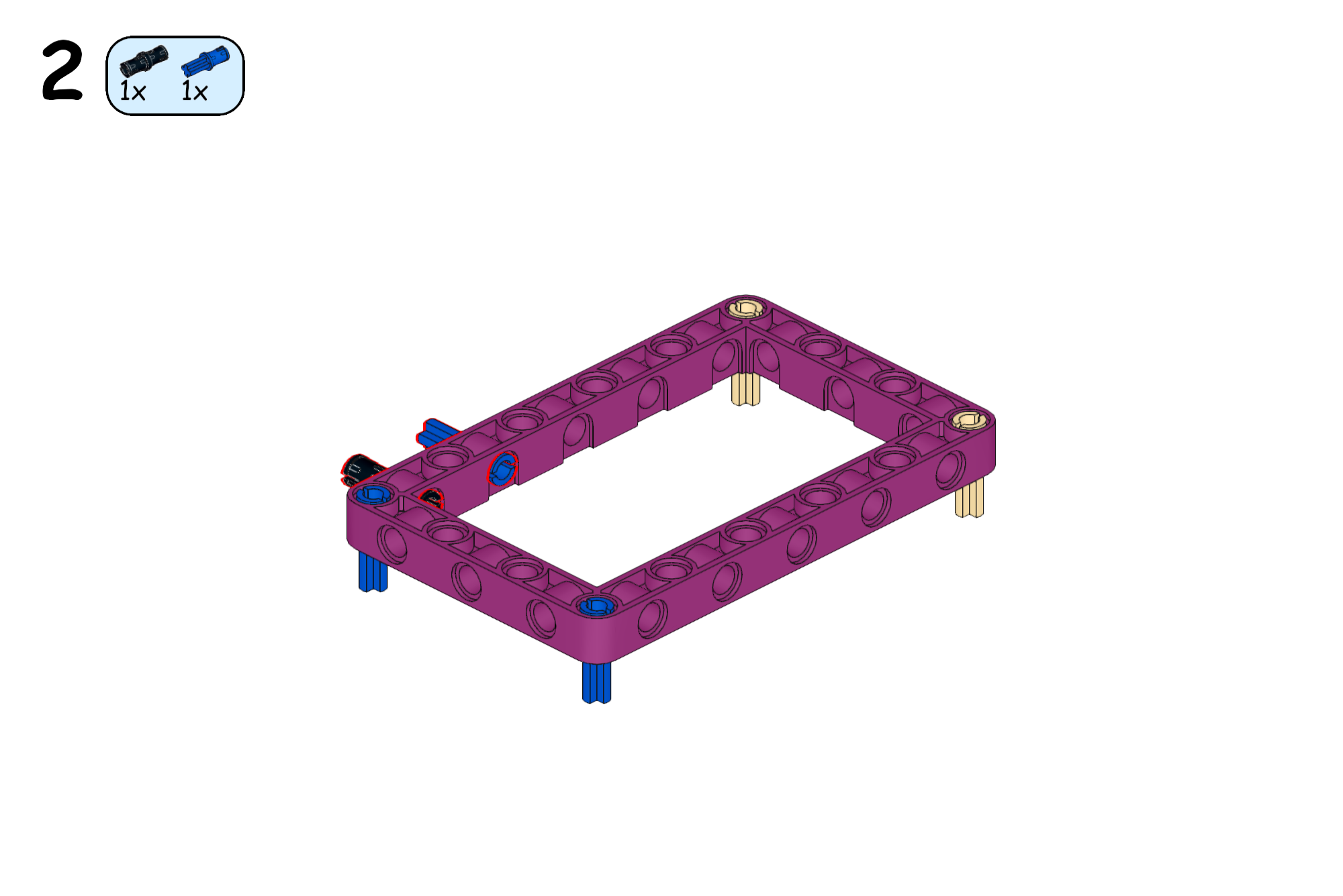
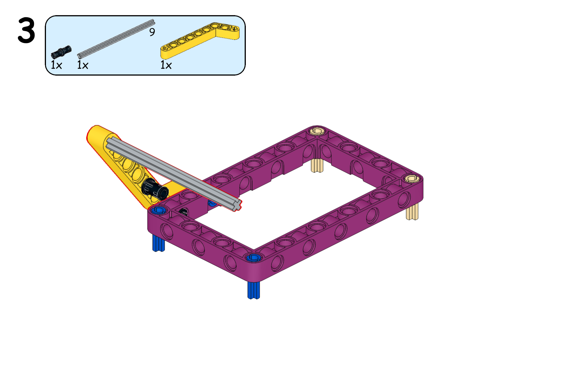
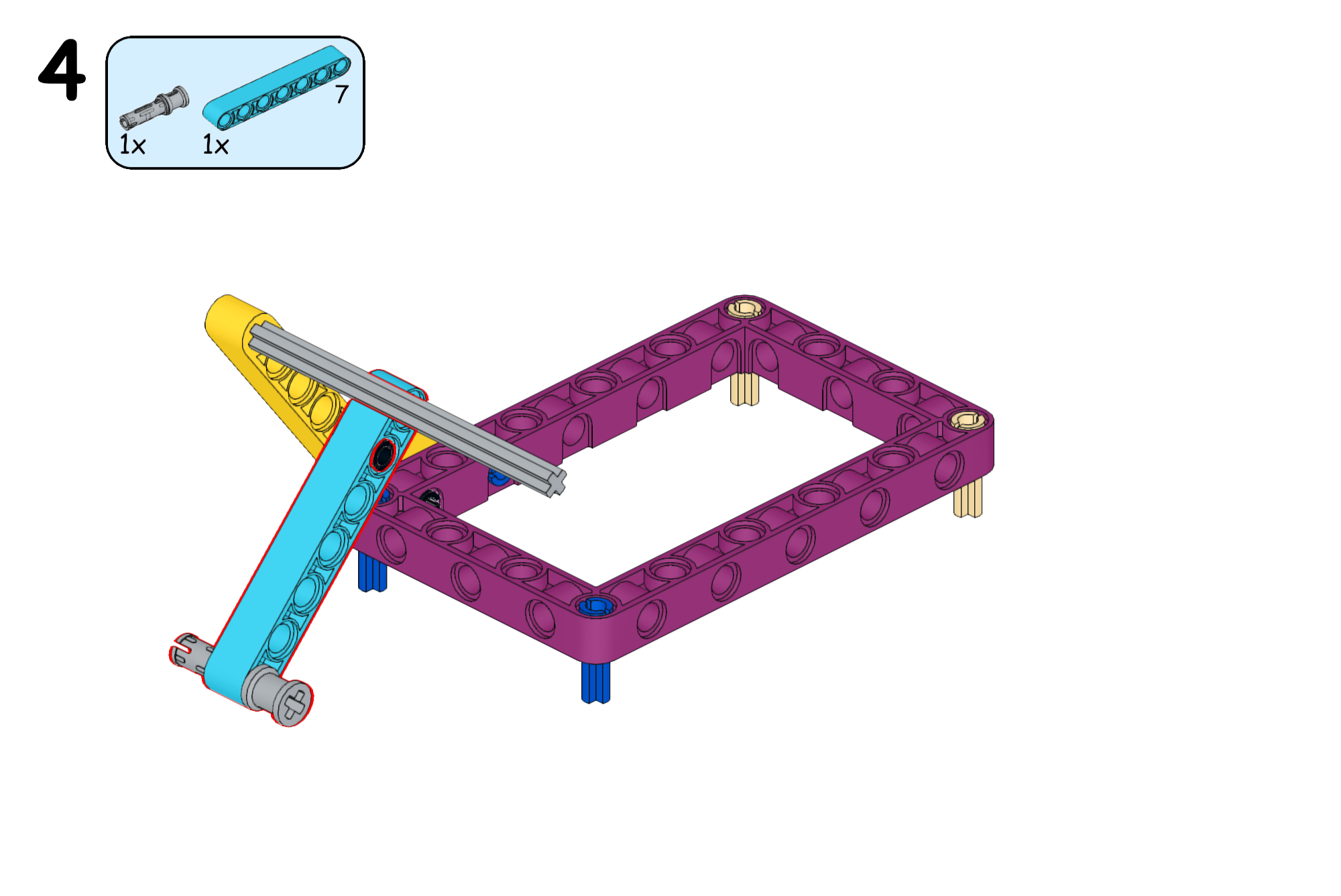
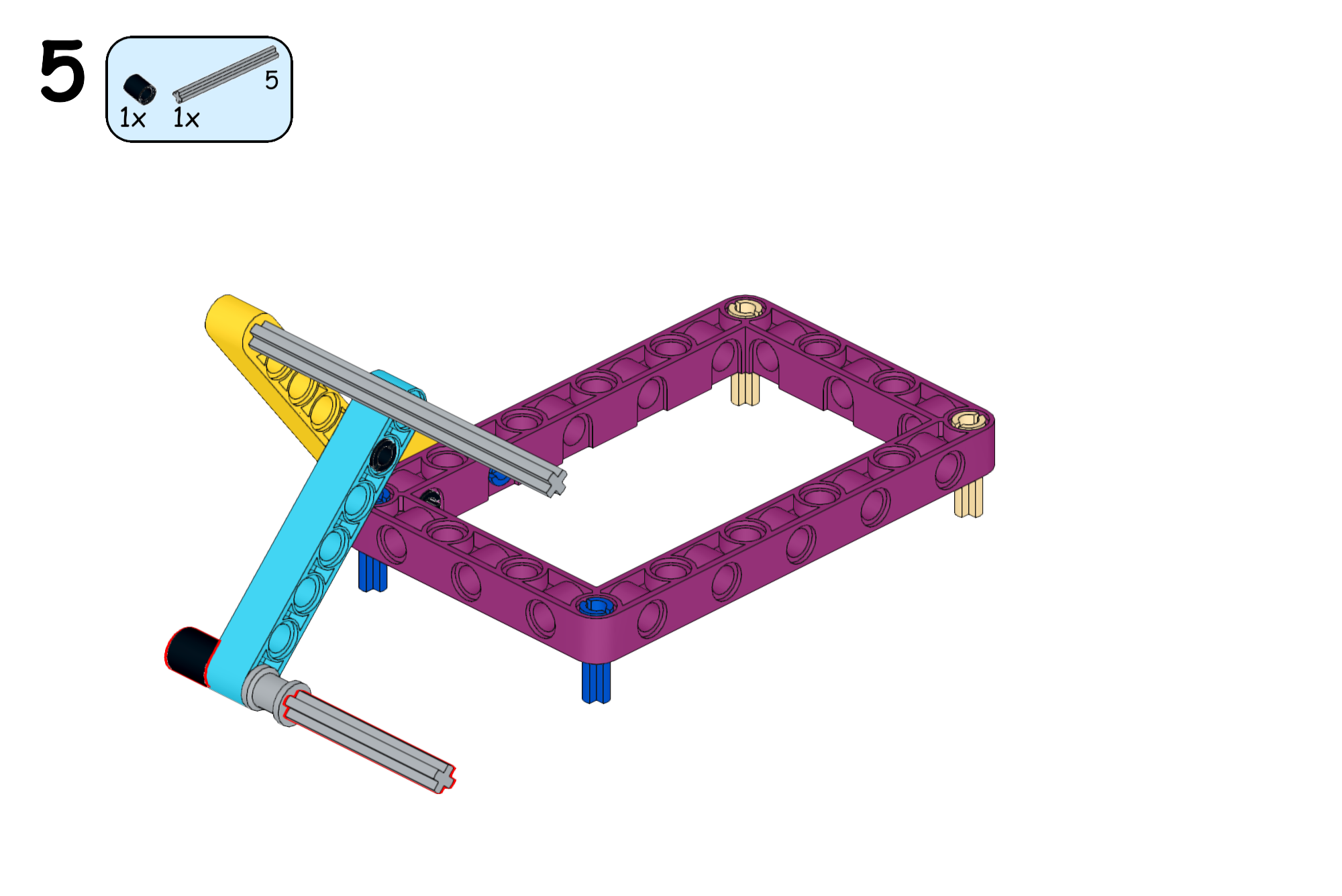
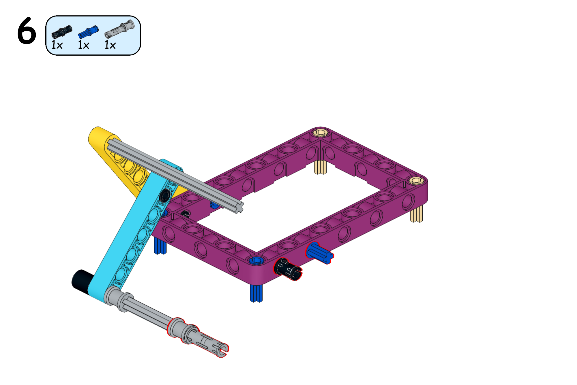
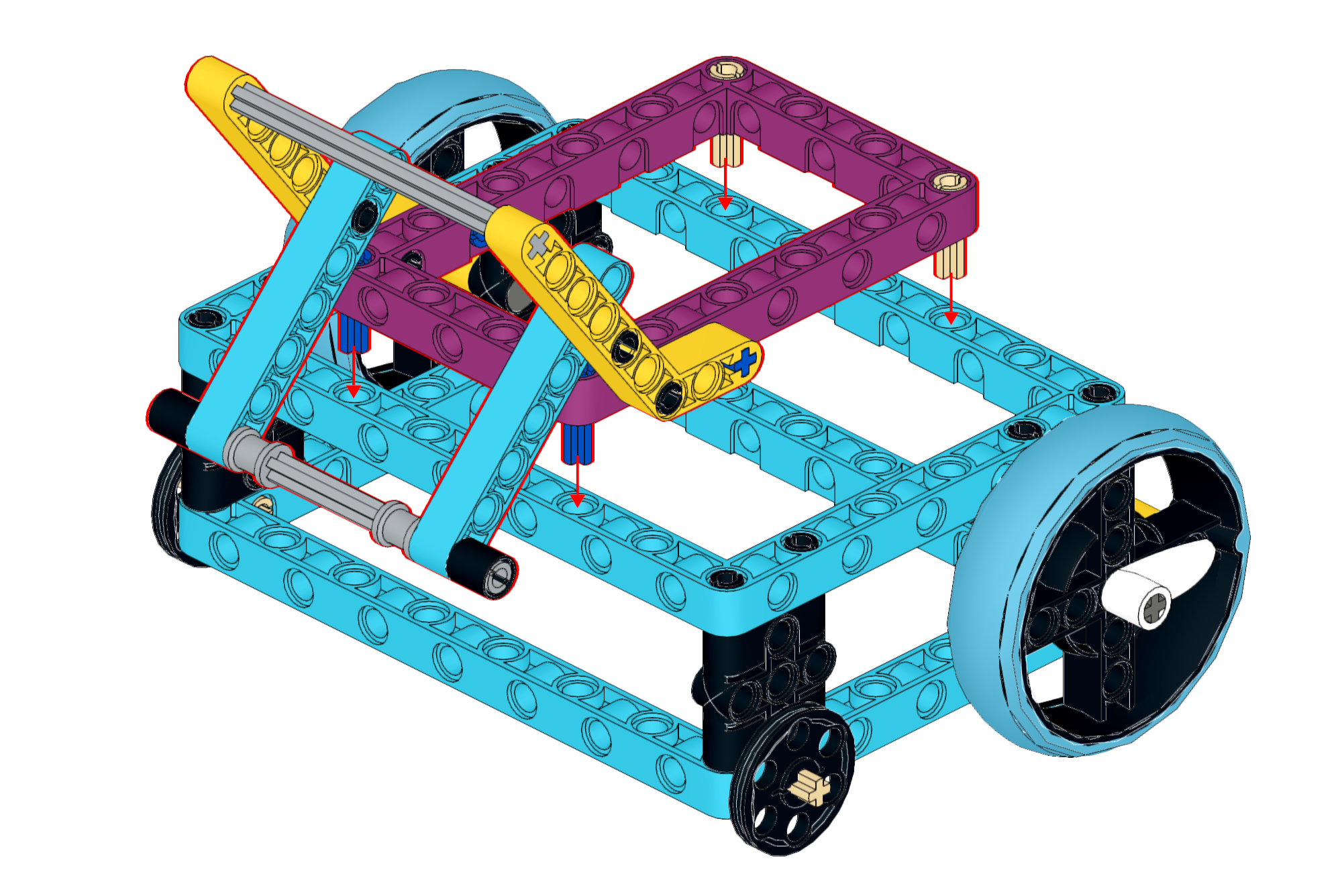
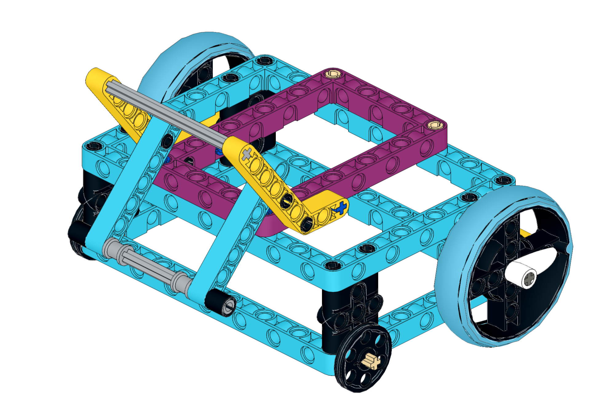
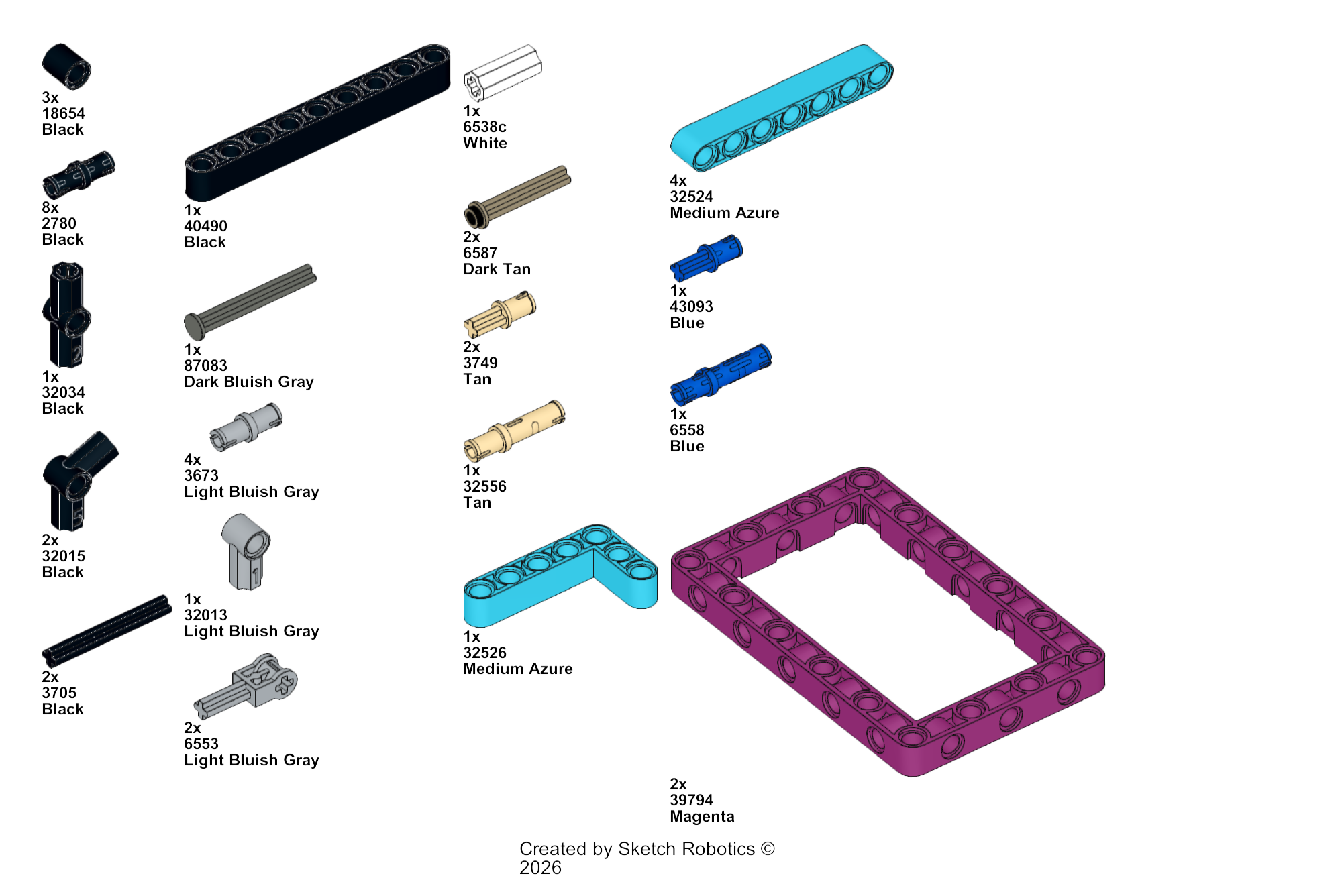
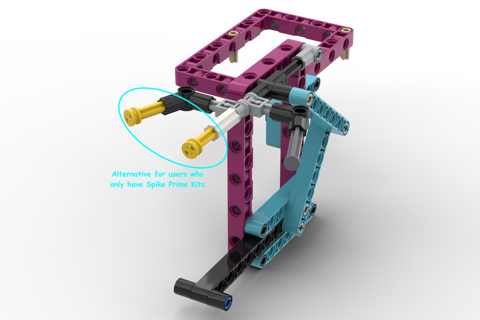
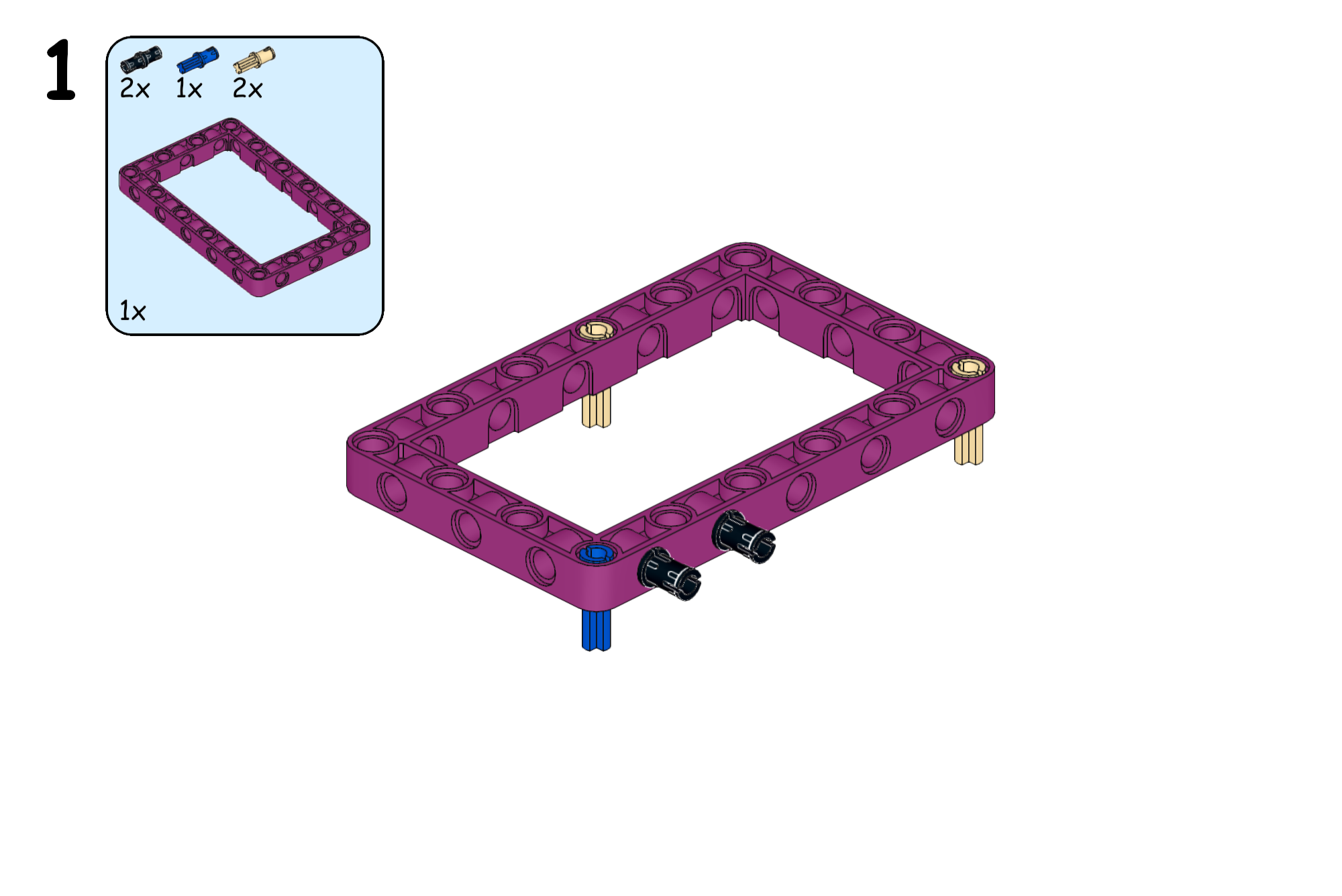
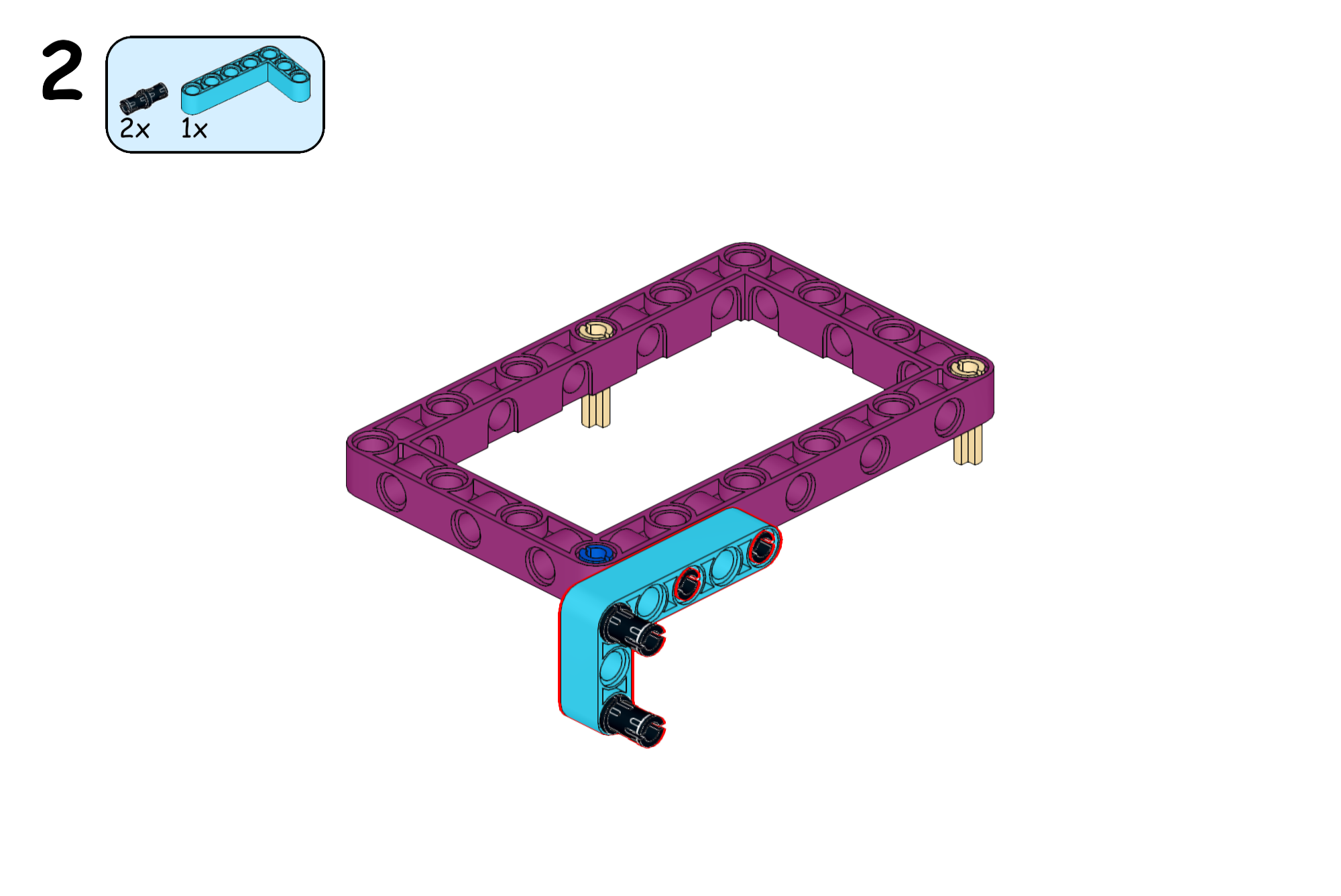
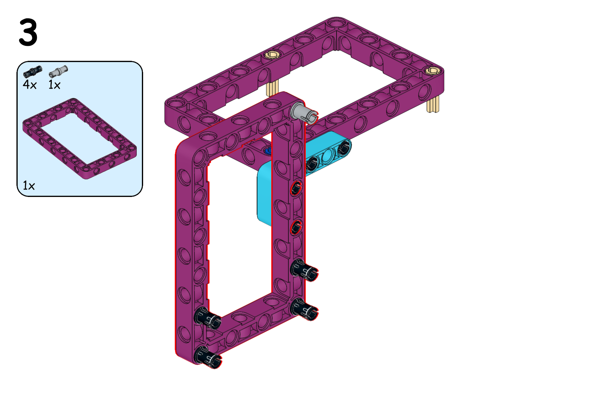
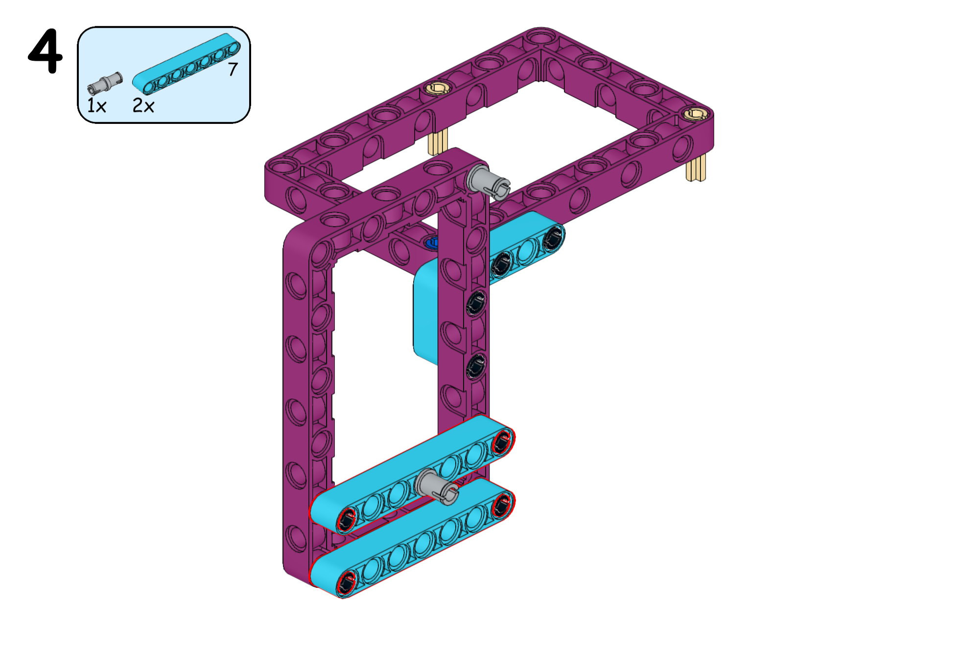
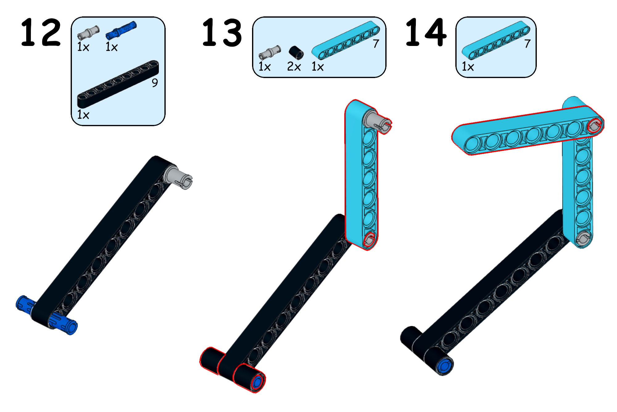
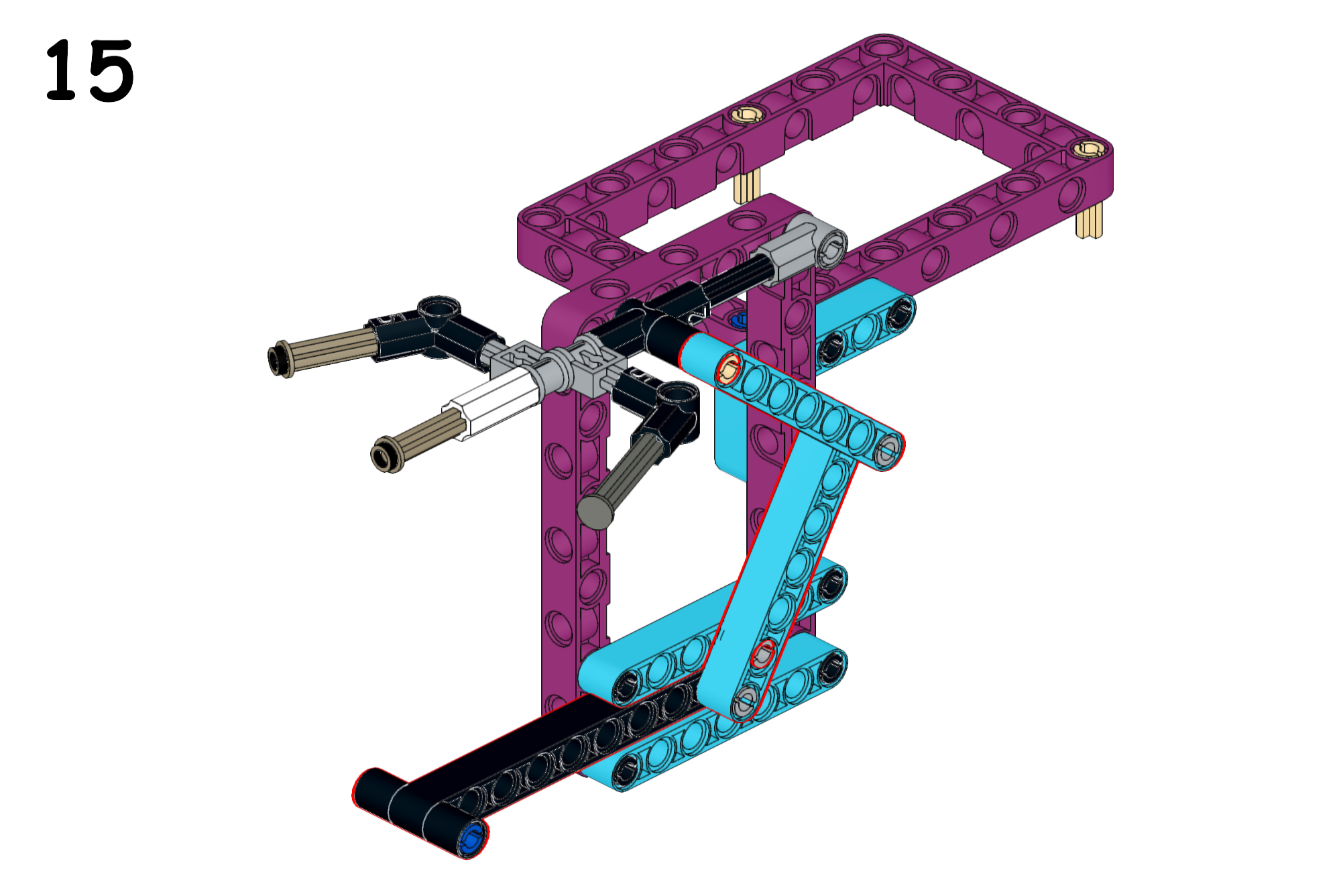
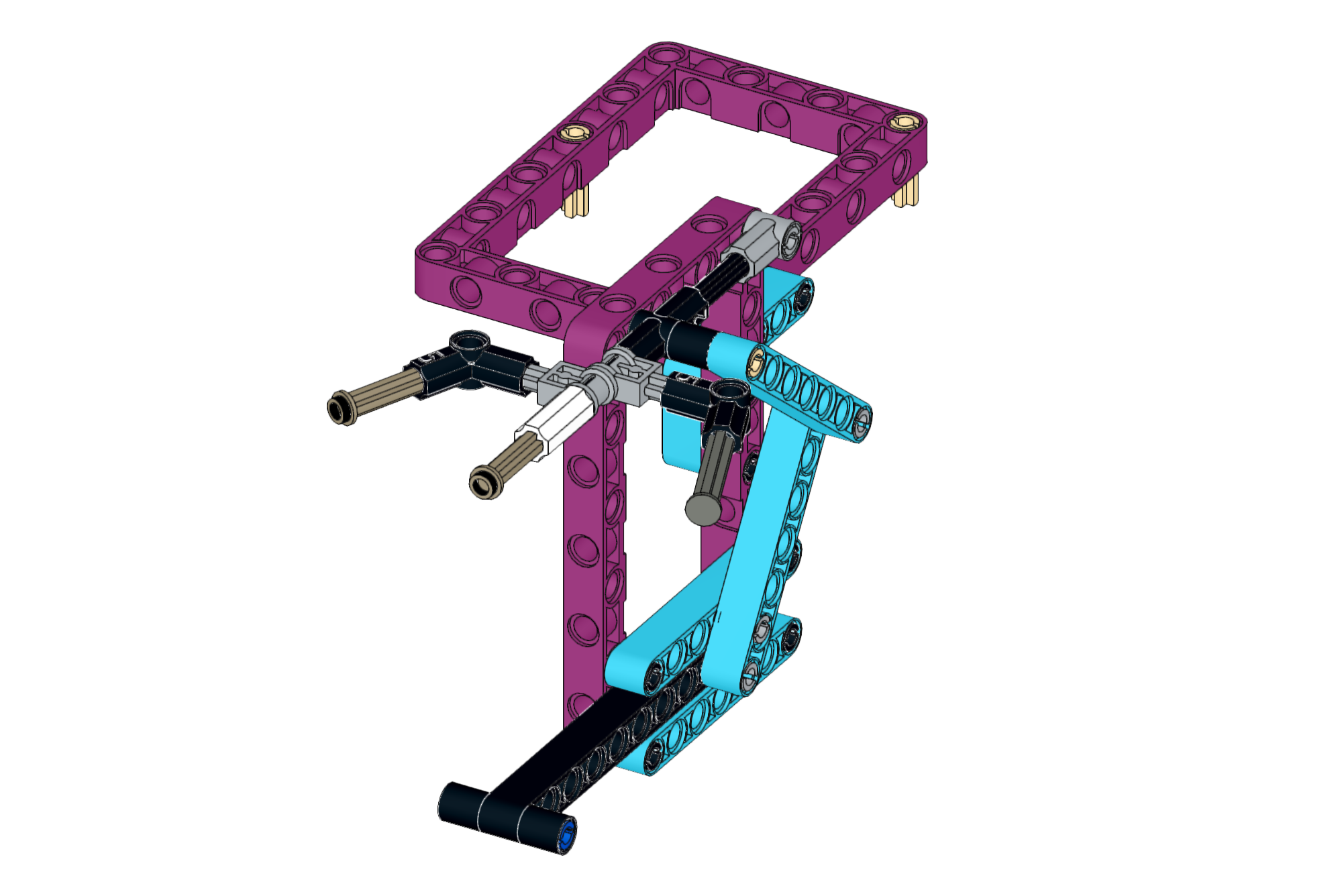
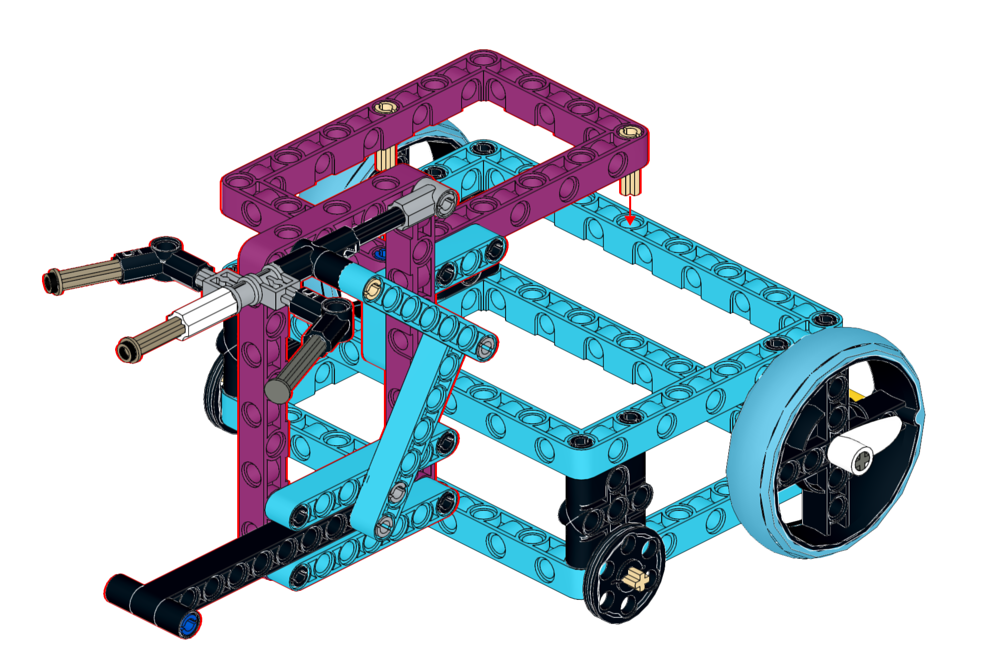
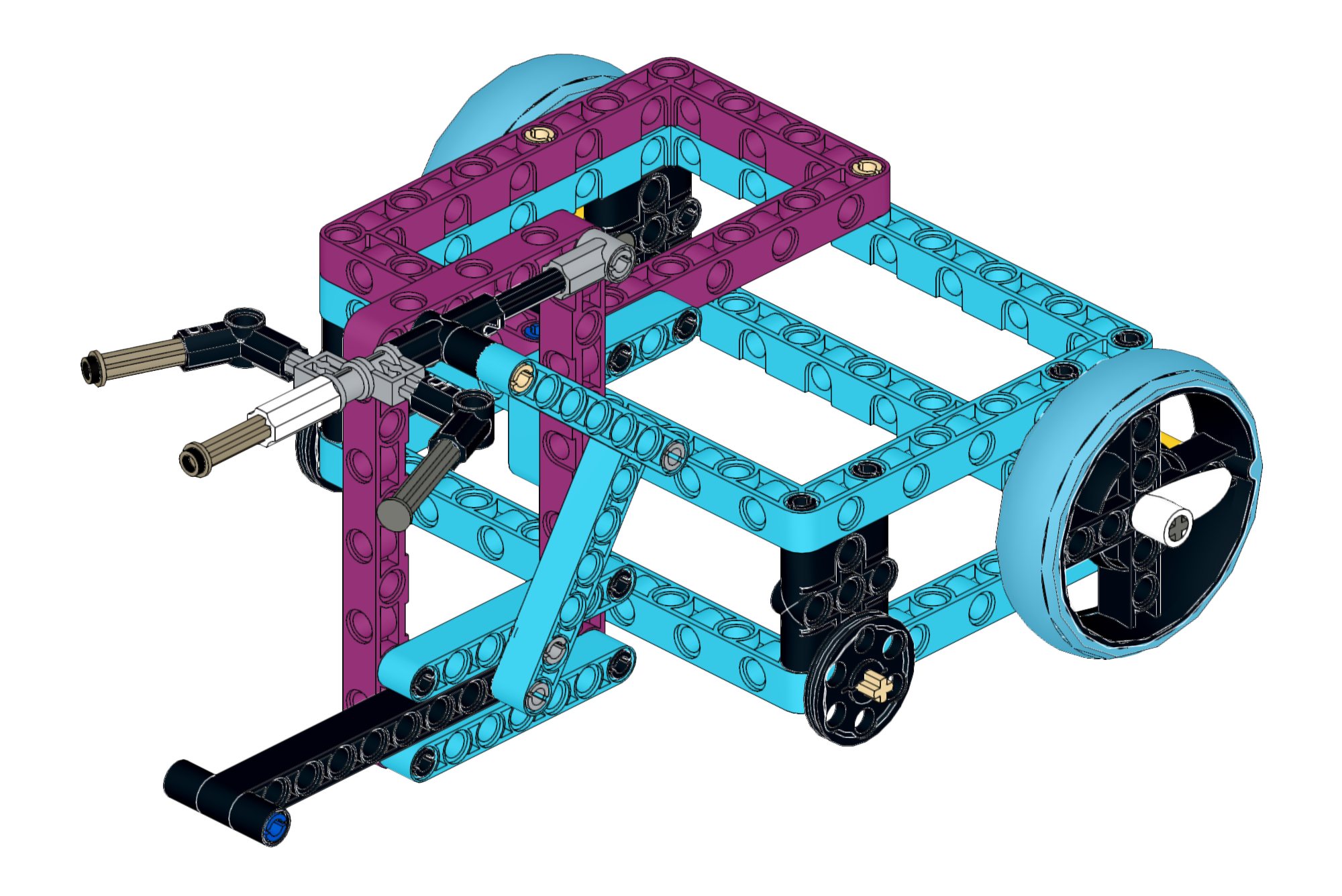
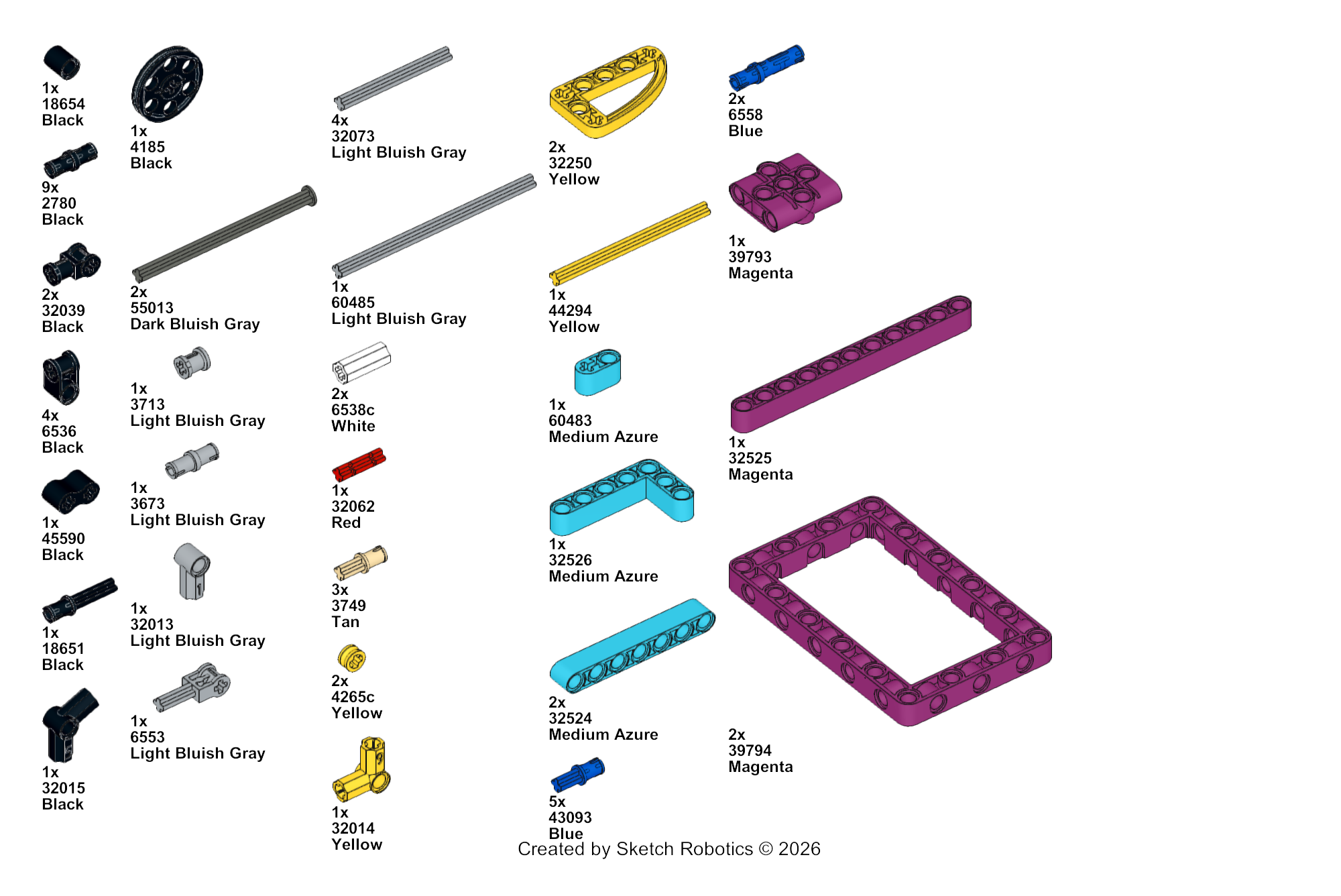
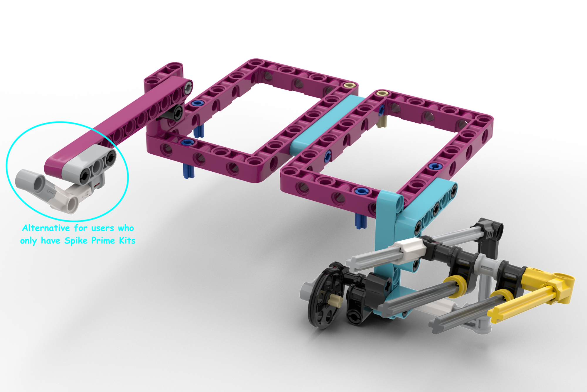
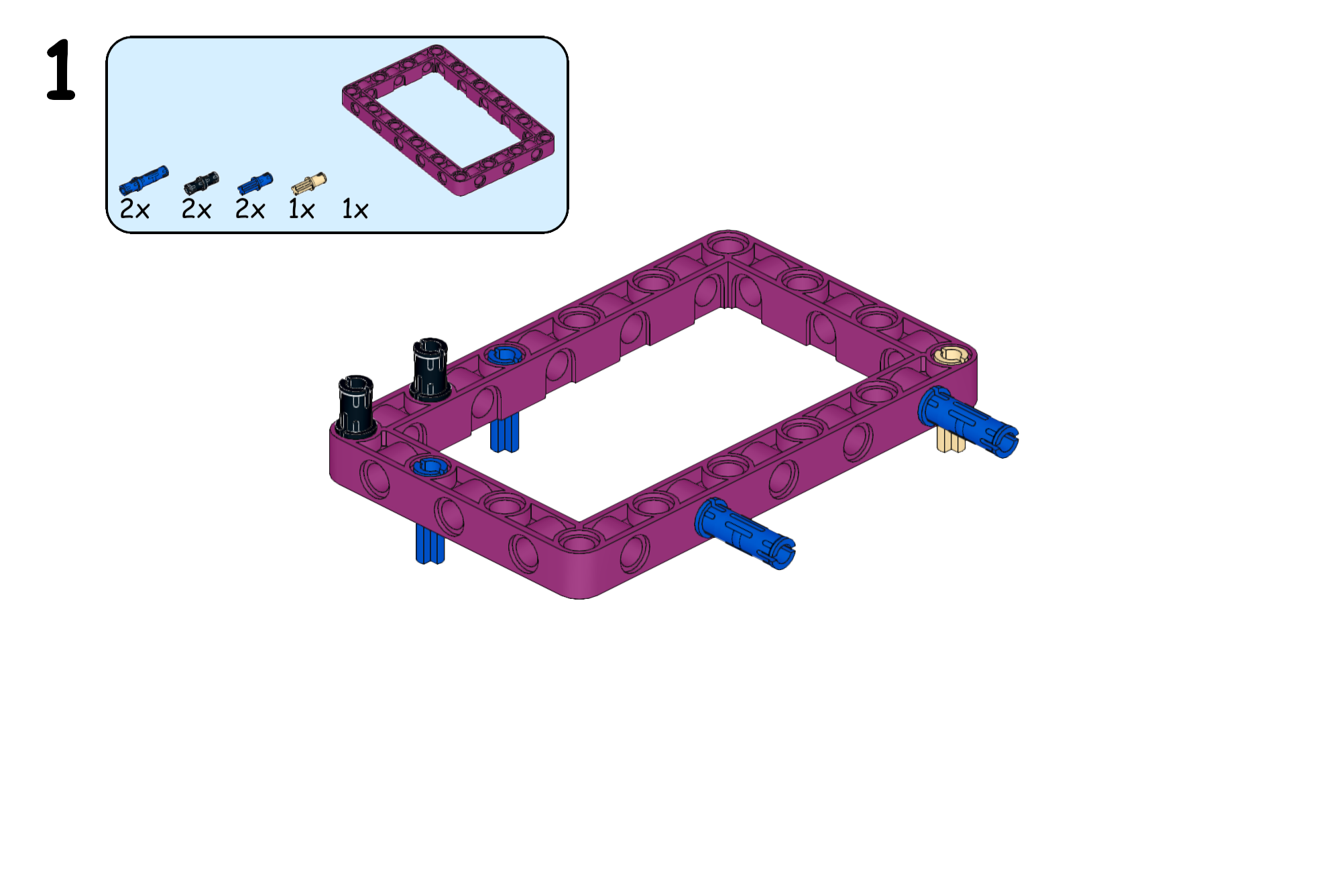
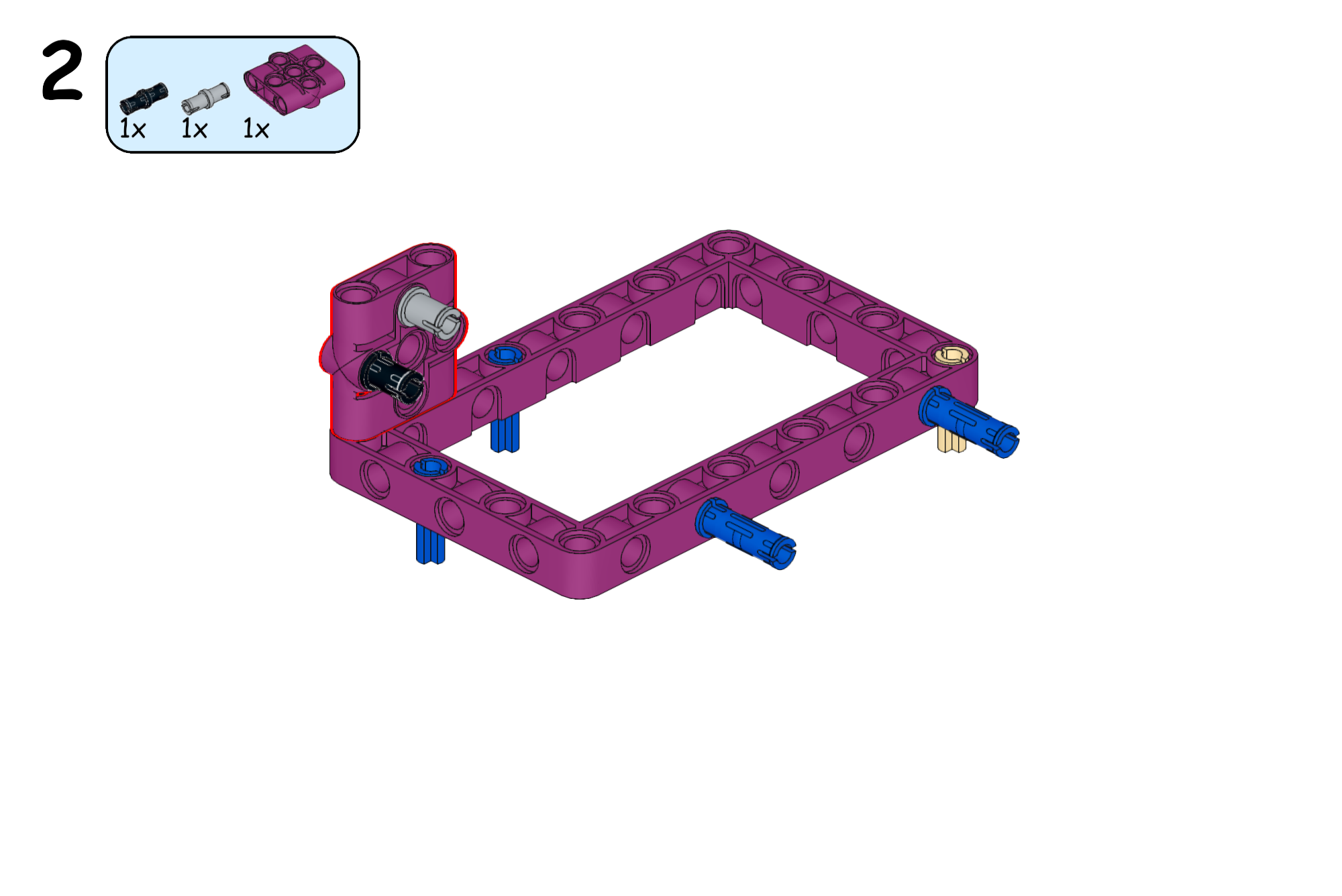
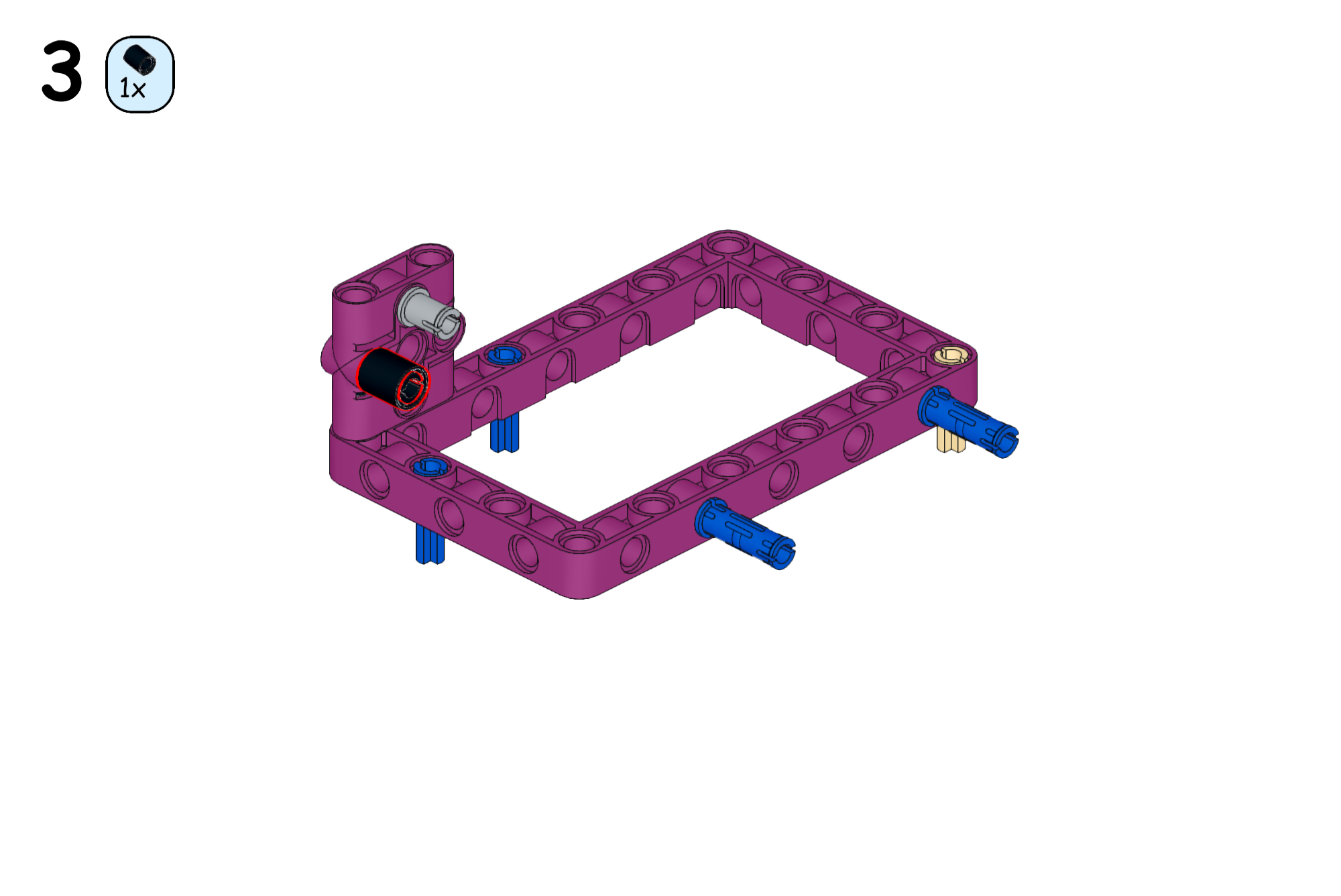
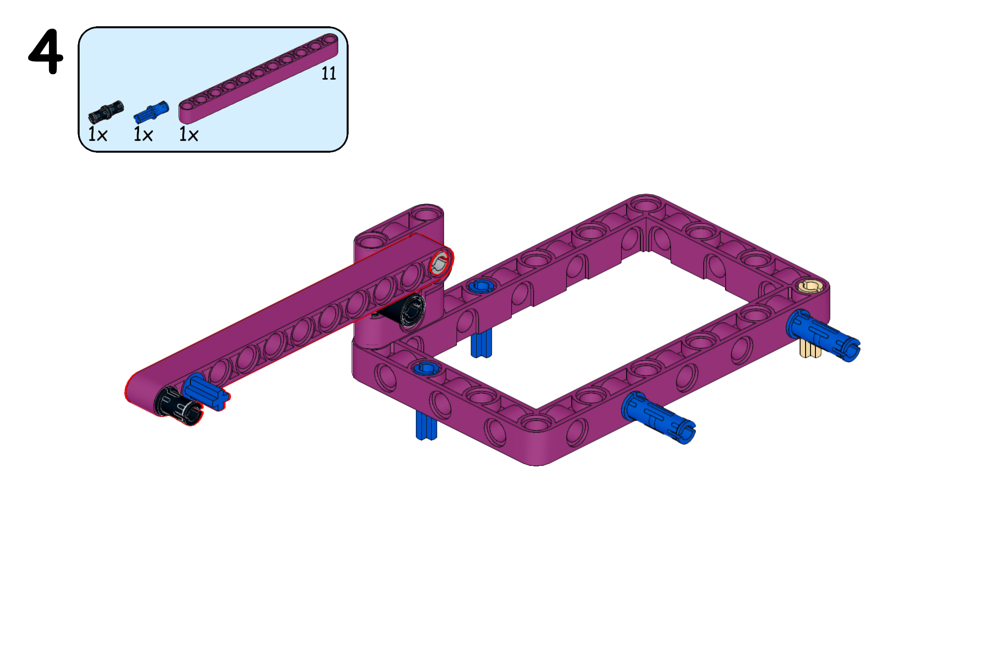
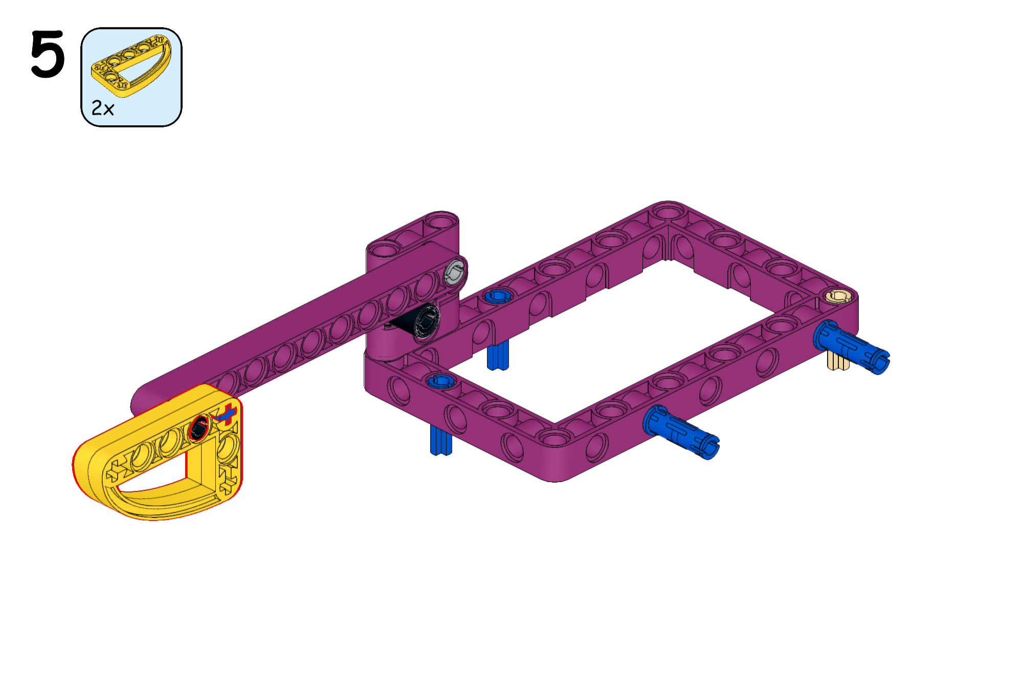
In this first chapter, we’ll explore the movements required to complete several BIOGLOW missions using a simple robot frame without motors. You’ll also build a selection of attachments containing passive mechanisms, gripping mechanisms, and mechanisms that will eventually be motorised.
There is no programming at this stage. Instead, the robot and attachments are moved by hand so that you can concentrate on understanding the missions and discovering what the robot actually needs to do.
By separating the movement from the motors and programming, we can study each mechanical problem more carefully. Once we understand the required movement, we can begin thinking about how a motor, attachment, or program could reproduce it reliably.
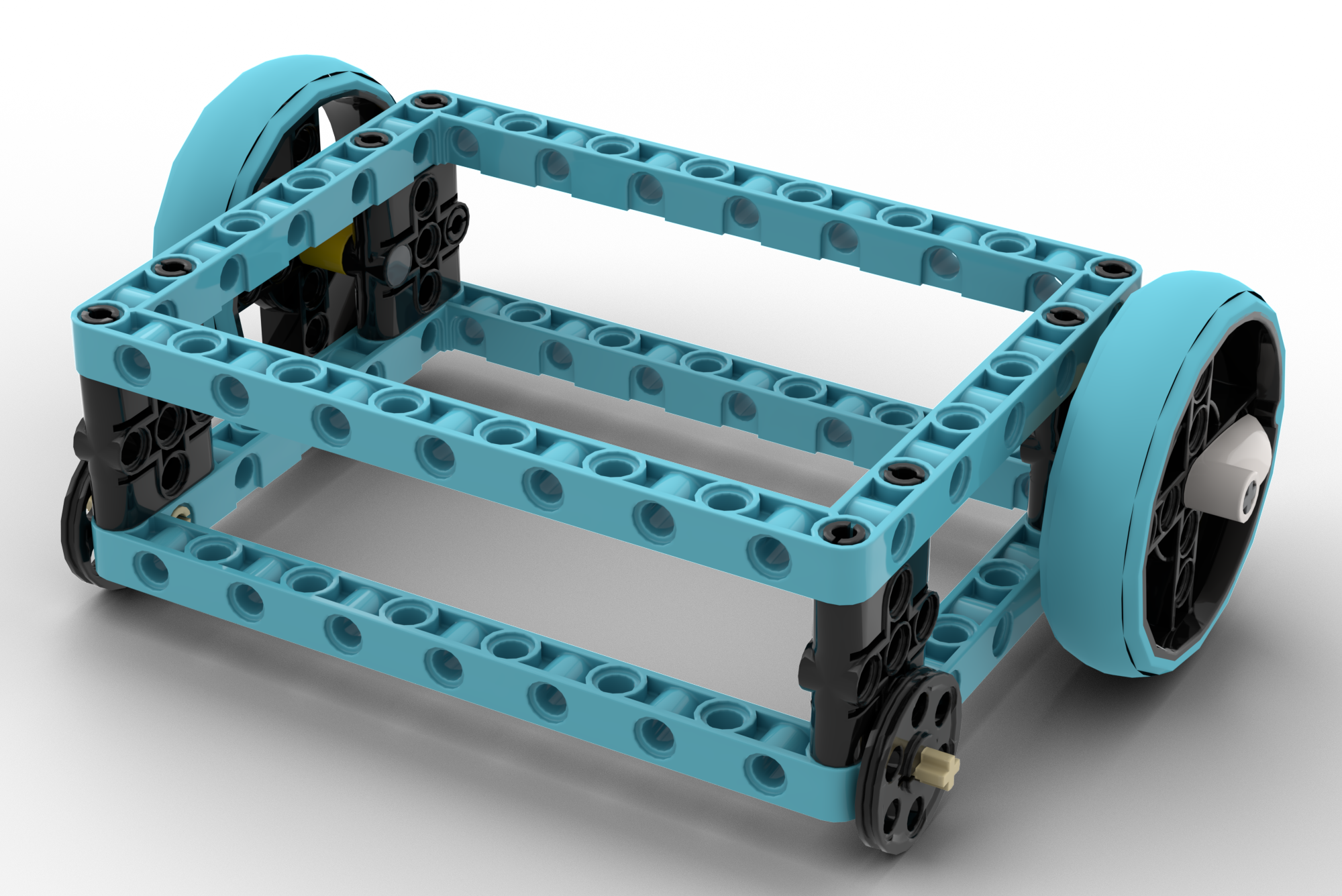
To describe how our attachments rotate, we will use three coordinate axes relative to the robot.
These axes give us a simple way to describe not only what a mechanism moves, but also how that movement takes place.
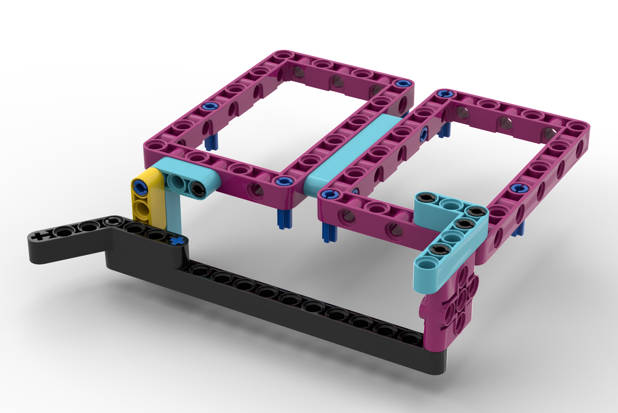
00:00 The first demonstration is Drone Survey (M01). Here, the attachment uses a long arm that rotates about the Z-axis. Because the Z-axis is vertical, the arm sweeps horizontally across the field.
As the mechanism is operated by hand, the arm pushes the scan marker until the drone is no longer touching the mat and the LiDAR map is completely flipped. At this stage, pay particular attention to the direction of rotation, the position of the pivot, and how far the arm needs to travel. Later, these observations will help us decide how a motor can reproduce the same movement.
An axis of rotation is an imaginary line around which a part turns. In Mission 01, the attachment arm rotates around the vertical Z-axis.
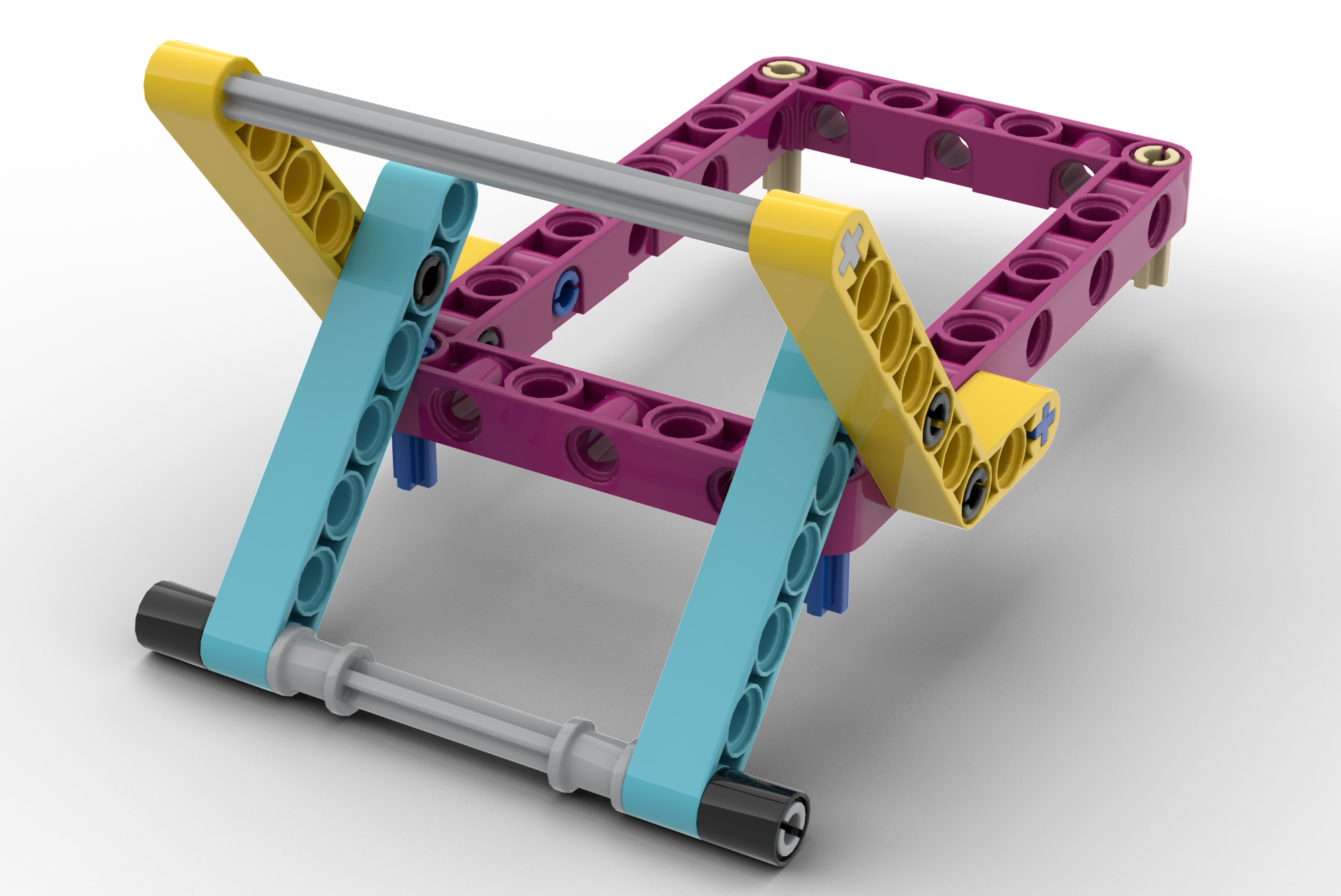
00:50 For Exploding Seeds (M02), we explore a gripping mechanism. Unlike the Drone Survey arm, this mechanism rotates about the X-axis — the horizontal axis running from the left side of the robot to the right side.
The attachment is positioned around the mission model and operated by hand so that we can concentrate on understanding the gripping action before thinking about motors or programming.
This separates two important engineering questions: What movement should the attachment make? and How will the robot create that movement? For now, we focus on the first question. The same X-axis orientation will appear again later when we explore Reaching Roots.
A gripping mechanism is designed to hold, capture, squeeze, or control an object. The exact shape and motion of the grip depends on what the mechanism needs to interact with.
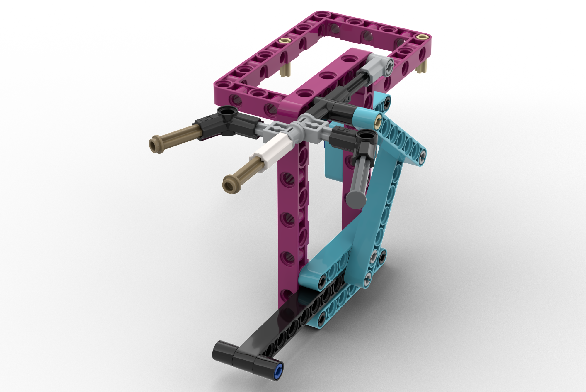
01:15 Lucky Leaves (M04) introduces a different design idea. The attachment does not need its own motor to perform the demonstrated action. Instead, the mechanism is triggered when part of the attachment makes contact with the base of the nest structure.
As the robot frame moves forward, its linear motion is used to create the rotational motion that lifts the leaves. In other words, the robot moves in a straight line, but the attachment converts that movement into rotation.
The mechanism can also be adjusted so that it picks up the two leaves while leaving the katydid behind. This demonstrates an important design principle: producing the correct type of movement is only part of the problem. The amount and range of that movement can be just as important.
A passive mechanism works without its own motor. Instead, it gets the movement or force it needs from another source — for example, the robot driving forward, the robot reversing, gravity, a spring, or contact with a mission model.
Before the match begins, the leaves are randomized within the nest, and teams are not told the starting position of the katydid. The updated mission constraints also make the position of the katydid within the leaf habitat an important part of your strategy.
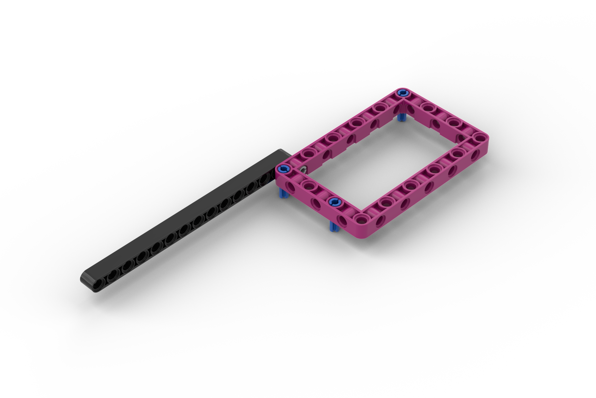
02:24 In Reaching Roots (M05), a long beam rotates to interact with the plant-root mechanism. Like the gripping mechanism explored in Mission 02, this arm rotates about the X-axis.
At this stage, we simply create and observe the movement by hand. Later in the course, the challenge will be to take rotation from a motor and transfer it to this horizontal axis so that the arm can perform the same action automatically.
We will also need to think about how quickly the arm should move and how much turning force is required. A mechanism that moves too quickly or does not produce enough force may not interact with the mission model reliably.
Torque is the turning force produced by a motor or mechanism. More torque allows a mechanism to apply a stronger turning force, although increasing torque often means the mechanism will move more slowly.
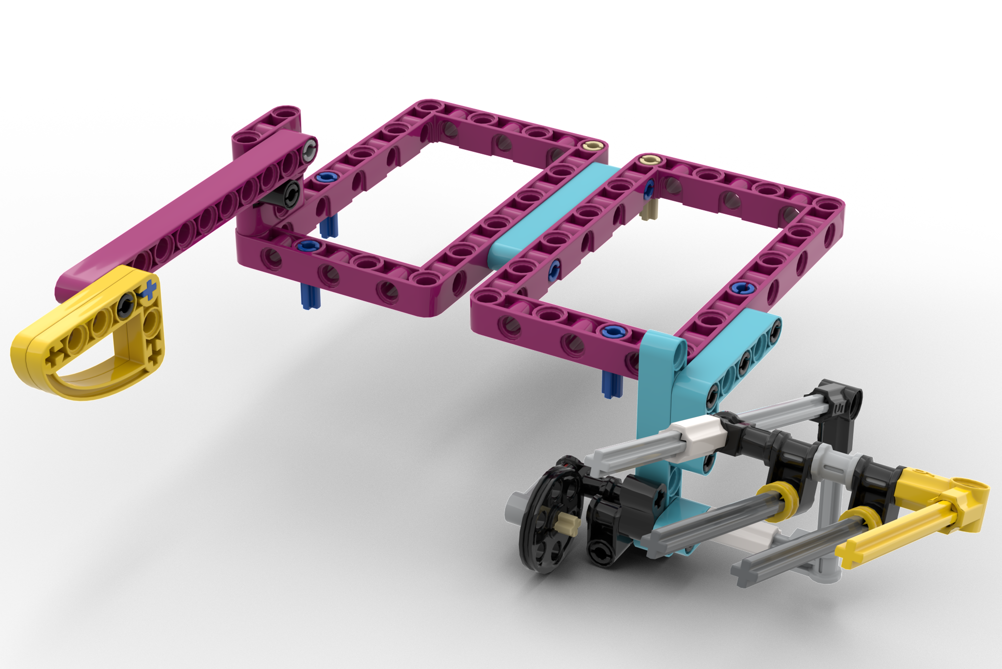
02:47 Finally, Window to the Past (M11) demonstrates how multiple useful actions can be built into one passive attachment.
As the robot approaches the root cover, the mission model itself triggers part of the mechanism. On one side of the attachment, a component rotates upward to collect a seed. On the other side, another part of the mechanism engages with and locks onto the root cover.
The robot can then reverse toward the Home Area. Instead of requiring another motorised action, the robot’s backward movement is used to pull the root cover down. This is a useful example of how the robot’s own movement and the geometry of a mission model can sometimes provide the motion an attachment needs.
This chapter is not about finding finished mission solutions. It is about understanding the various movements before designing the robot that will recreate it.
By moving the frame and mechanisms by hand, we can separate the mechanical problem from the programming problem. We can observe where an attachment needs to rotate, what should trigger it, how far it needs to move, and whether the robot’s own forward or backward motion can be used to make something happen.
As you explore the examples in this chapter, start asking:
These questions will become an important foundation for the rest of the course.
Once you understand what the robot needs to do, we can begin building BLOOM — the evolution of our Archy robot from the Unearthed season — and start turning these hand-operated movements into reliable mechanisms and programs.
First explore the movement. Then build the mechanism. Finally, bring it to life with code.
These terms have been introduced in this chapter. We will continue adding new words and concepts to the course glossary as you progress.
X-axis: The horizontal axis running from the left side of the robot to the right side.
Y-axis: The horizontal axis running from the front of the robot to the back, along its normal driving direction.
Z-axis: The vertical axis running upward, perpendicular to the field mat.
Axis of Rotation: An imaginary line around which a part rotates.
Linear Motion: Movement along a straight path.
Rotational Motion: Movement around an axis.
Gripping Mechanism: A mechanism designed to hold, capture, squeeze, or control an object.
Passive Mechanism: A mechanism that works without its own motor and receives its movement or force from another source.
Speed: How quickly a part or mechanism moves.
Torque: The turning force produced by a motor or mechanism.

 Google